|
Noise emissions from large-scale heat pumps |
|
Large heat pumps are particularly suitable for use in industry, in municipal infrastructure or in large residential and commercial buildings.
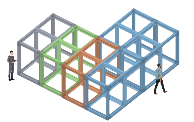
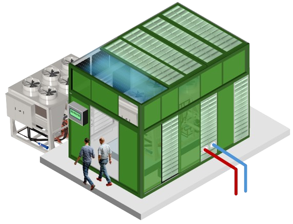
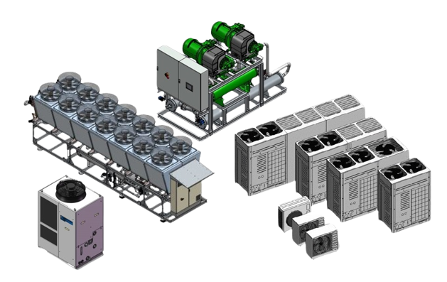
While heat pumps for use in private residential and commercial buildings are now standard in heating technology and are increasingly pushing back the use of condensing boiler technology, there is still great potential in the broad market launch of large heat pumps or industrial heat pumps in the output range from 200 kW to > 1,000 kW. In many cases, these systems are also used as part of district heating networks or in combination with recoolers in order to be able to operate the systems at optimum bivalence points. The use of these systems, which are usually equipped with multiple compressors and fans and which move large volumes of air, is a problem for residents in densely built-up urban areas. Thanks to the modular design of our acoustic enclosures, individual modules can be built into complex overall solutions to accommodate individual systems or system combinations with attachments, for example for the pipework and/or for the entire electrical system. |
Simulation of air flow and air velocity |
|
In contrast to water-cooled heat pumps and refrigeration systems, the required air volume is at the centre of sound insulation measures for air-cooled systems in order to prevent power and pressure losses in the systems.
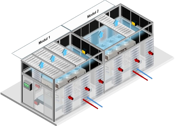
We differentiate between the following principles of air routing for sound insulation: Systems with horizontal air flow (air inlet and air outlet are horizontal) Systems with vertical air routing (air inlet at the bottom / air outlet at the top) Systems with combined air ducting (air inlet at the side / air outlet at the top) The majority of the systems listed above are equipped with axial fans with a static pressure of between 20 and 80 Pa. |
Systems in the lower output range usually only have a maximum static fan pressure of 20 Pa, while larger systems, where heat recovery is also an issue, for example, have a much higher pressure. The first resistance that fans have to overcome is pressure loss when air enters the evaporator.
In addition, with most axial fans, the air is not discharged centred above the fan, but the greatest air volume and air speed is achieved at the edge of the fan blades. This must be taken into account when measuring the air volume and air speed of systems, as these values can increase by up to 60% from the fan centre to the outer edge of the fan. This prevents incorrect plan data from being used.
The design of acoustic enclosures for air-cooled systems is primarily based on the required air volumes of the systems and the desired air velocities; the physical dimensions of the systems are only of secondary importance when planning acoustic enclosures.
For an air volume of 6,000 m3/h, a free air inlet and outlet area of 0.83 m2 is already required to keep the air velocity at 2 metres/sec. The free area means the net area without grille or louvre structures.
For a large heat pump with a required air volume of 250,000 m3/h, the net free air inlet and air outlet areas are already 36.11 m2 at a planned air velocity of 2 metres/sec. It goes without saying that practically no noise reduction can be achieved with this free area (sound bridge). Here, the planned air velocity must be raised to a higher level; an air velocity of 6 metres/sec. already reduces the required free area to 12.04 m2 and thus optimises the sound insulation many times over.
In conclusion, standardisation of acoustic enclosures based on system size falls short and can lead to performance losses in the systems that often go unnoticed, regardless of whether this concerns acoustic enclosures with baffles, acoustic enclosures with targeted air routing or supply air and exhaust air acoustic baffles. The simulation or calculation of the air supply to the evaporators and condensers and the removal of cold air is a decisive factor when planning acoustic enclosures.
Sound enclosures modular frame structure |
|
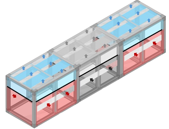
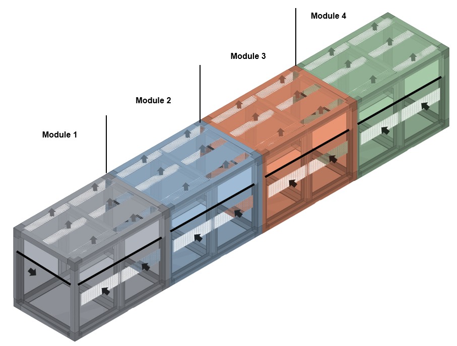
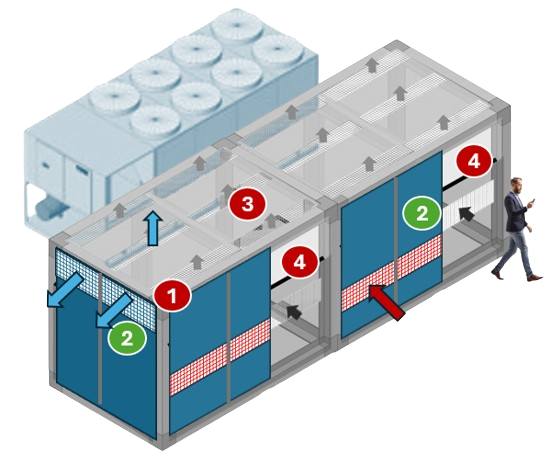
The basic structure of the acoustic enclosure consists of individual modules made of aluminium plug-in profile frames. In the example below, 4 individual modules were connected on site to form an acoustic enclosure.
The air inlet openings and air outlet openings and the service doors around the system are integrated into the profile frames. The service doors are based on aluminium panels with a thickness of 1.5 mm with 40 mm thick Stratocell® Whisper insulation on the inside. The sound enclosure example shown below for 2 sound enclosures mounted one behind the other consists of 4 modules which, when assembled, have the following dimensions: 13,600 x 3,400 x 3,222 mm (L x W x H) with a weight of 2,322 kg. The free surfaces of the air inlet and air outlet openings are designed for an air volume of 650,000 m3/h. The air flow is offset to the side so that no air short circuit can occur between the exhaust air and supply air. The air inlet is on the left or right on the narrow side of the bonnet, the air outlet on the long sides at the top. By deflecting the air by 90°, the airborne sound is broken up and the air outlet speed is reduced to around 5 to 6 m/sec, which leads to a significant reduction in the outlet noise. |
Sound enclosure construction |
|
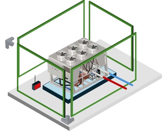
The basic structure of the acoustic enclosure is an aluminium plug-in profile frame into which the service doors around the system are integrated. The service doors around the system can be easily removed with a tilt dimension of 6 cm and allow unhindered access for service and maintenance work on the systems. They are installed on a level concrete foundation in the basic dimensions of the acoustic enclosure.
The service doors are based on 1.5 mm thick aluminium panels with 40 mm thick Stratocell® Whisper insulation on the inside, which has some of the best sound-absorbing properties available on the market. As the laminated polyethylene foam absorbs noise and does not reflect it, it is an excellent alternative to many of the noise protection materials used today. The insulation is also moisture-resistant, does not build up mould, can be rinsed with a high-pressure cleaner and complies with fire protection class: B-S2-d0 (flame retardant). The air openings and the free air inlet openings are designed at around 7% above the required air volume of the system. The air routing is offset to the side so that no air short circuit can occur between the exhaust air and supply air. |
1)
Alluminium base frame adaptable to all system sizes, required air volumes and installation situations 2) Service doors around the units with a tilt dimension of 6 cm 3) Roof panels with a tilt dimension of 6 cm for unrestricted access to the fans. The roof panels are designed for a load of 160 kg/m2 4) Air chamber separation and freely selectable air routing |
Project-specific acoustic enclosures for large systemsLarge heat pumps and air- and water-cooled refrigeration systems |
|
Large heat pumps and air- and water-cooled refrigeration systems
Thanks to the modular design, individual modules up to 6 metres in length and width and a height of around 3.5 metres can be easily realised. Larger systems or several systems can also be equipped with a sound enclosure by combining individual modules. Attachments for pipework, electrical cabinets or simply for escape routes can also be realised. Customised products for the following situations: 1 ) Enclosure of several systems, even with different dimensions. 2 ) Various combinations of air ducting. 3 ) Heat recovery. 4 ) Combination with pre-cooling |
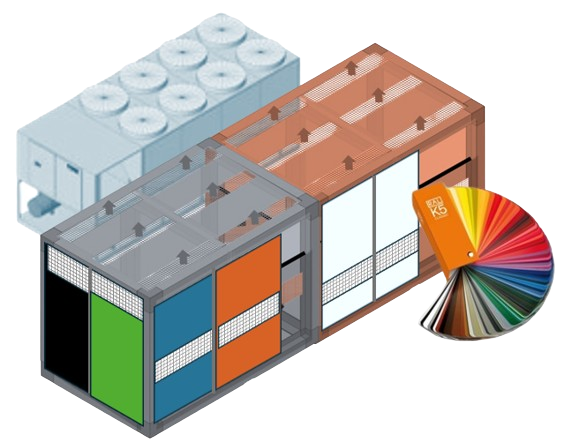
Free choice of RAL exterior colour for your acoustic enclosure |
|
I would like to find out what colour a physical object is (example facade) How do I do this?
We recommend comparing the colour of the object with the colour samples in a physical colour fan. Please note that it may also be a RAL colour or a colour from another colour system used by a specific paint manufacturer, for example. You should also bear in mind that the colour on the object may have faded over time. RAL offers an electronic device that determines a RAL colour by "scanning" the object. |

