|
Noise emissions from air conditioning units and heat pumps |
In principle, sound levels of heat pumps and air conditioning systems are measured in test laboratories at a fixed frequency to give consumers an indication of the sound levels when comparing different products. These tests do not take into account the different operating states of a heat pump or air conditioning system, which means that in practice the sound levels are usually perceived to be higher than the manufacturers' published sound levels would suggest.
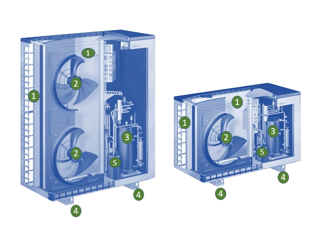
The noise sources for heat pumps and air conditioning systems in detached houses and smaller apartment blocks are as follows: compressor in the relatively low output range but modulating and therefore perceived as disturbing, fans with varying speed and, last but not least, the evaporator. The interaction of these components forms the noise spectrum of heat pumps and not a single frequency.
In this context, the background noise shortly before the defrosting cycle of heat pumps (humming) is perceived as highly disruptive. This is caused by a large pressure loss on the evaporator due to freezing fins, as the speed of the fan(s) is increased to compensate for the pressure loss and the compressor also operates at maximum power.
This entire superimposition of frequencies takes place here in the frequency range > 60 Hz. In addition, the tonality, which adds between 5 and 7 dB(A) to an A-sound assessment, is completely eliminated by the use of a sound bonnet. Measurement results obtained with a compressor or a fan do not reflect this interaction of the sound levels of a heat pump or air conditioning system and, in particular, do not take into account the background noise of systems in different operating states.
With a sound enclosure, it is therefore particularly important to ensure that other frequency ranges do not become more audible by switching off individual frequencies, so-called masking effects. This is achieved with our acoustic enclosures using 3 acoustic principles: Sound insulation, sound absorption and prevention of sound reflection. This is a combination of the internal insulation of the acoustic enclosure, the air deflection of 90° to break up air vibrations (conversion into energy) and the closed space of the acoustic enclosure. In this way, we can guarantee a sound reduction of 17 to 21 dB(A) over the entire frequency band from 63 to 8,000 Hz at a distance of 1 metre on all sides; in laboratory measurements, we also achieve up to -25 dB(A).
We also apply the same acoustic principles to the construction of large acoustic enclosures for heat pumps, air conditioning and refrigeration systems with outputs of several 100 kW.
|
Main sources of noise
1 ) Evaporator (depending on the model also over the corner) 2 ) Fans (axial or radial) 3 ) Compressors (also multi-stage, depending on the model) 4 ) System bearings (source of structure-borne noise) 5 ) Condenser Other sources of noise are improperly installed pipework, especially refrigeration pipes and water pipes that are not vibration-decoupled or have been installed with dents. Dents in refrigeration pipes can lead to a whistling sound during operation |
Sound enclosures for systems with horizontal air flow |
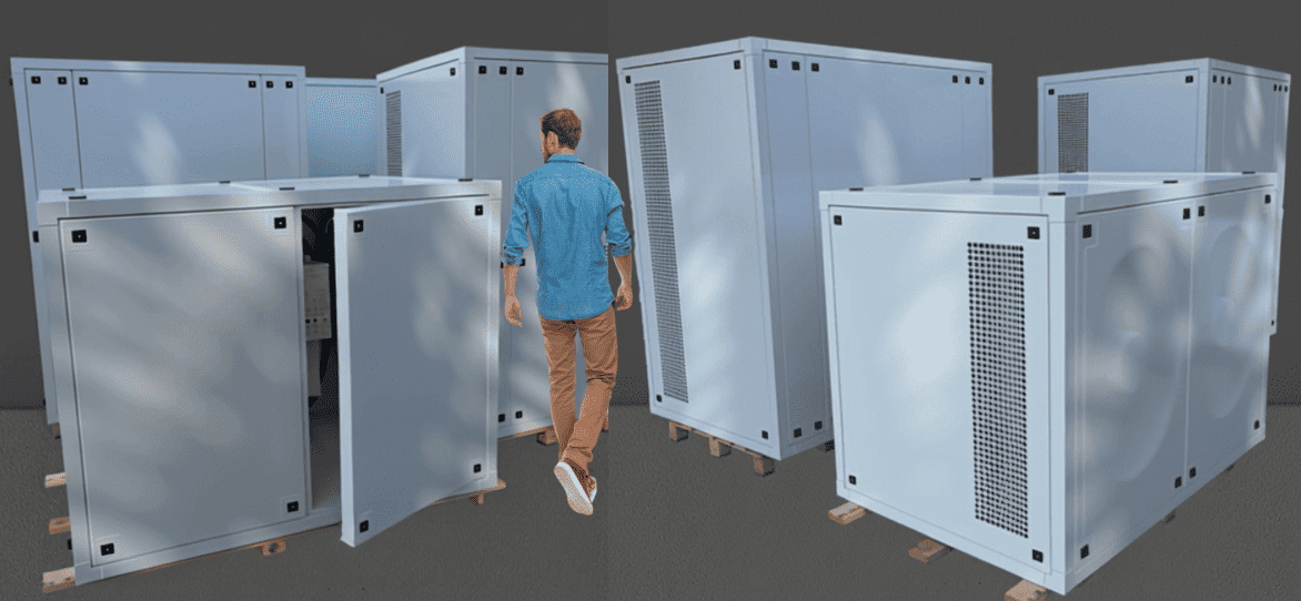
Our acoustic enclosures offer a simple but effective solution to reduce the noise of heat pumps, air conditioning and VRF/VRV systems with horizontal air ducting while improving aesthetics and safety.
Noise reduction down to -20 dB (A) without loss of efficiency, through sound insulation, sound absorption, prevention of sound reflection.
Protection against environmental influences and unauthorised access.
Housing for new systems and retrofitting of existing systems. Adaptable to any system size for systems with single fan and double fan.
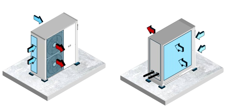
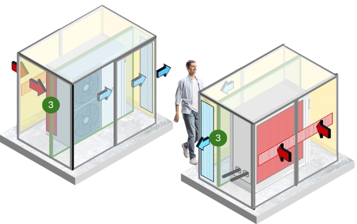
Operating in heating modeThe picture on the right shows the air flow without acoustic bonnet in heat pump operating mode. It should be noted that many systems also have lateral evaporator fins that must be supplied with air in order to avoid power losses in the heat pump and to guarantee complete defrosting during defrosting, including of the lateral evaporators.
|
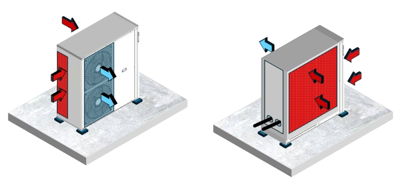
Operating in cooling modeMany systems today are operated in both heating and cooling mode, especially MINI-VRV/VRF systems. It should be noted that systems in cooling mode quickly trigger a high-pressure fault at very high temperatures and insufficient air supply. This must be taken into account when dimensioning the free air openings. We therefore always dimension our acoustic enclosures to a 10% higher air volume than that specified by the manufacturer at full load.
|
Sound enclosures Separation of air chambers |
|
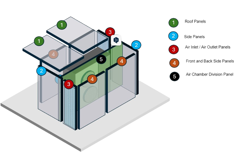
Correctly designed acoustic enclosures with a hermetic separation of the air chambers do not lead to a reduction in the system performance during annual operation.
This is the case if the pressure loss of the system does not exceed 20 to 25 pascals, as this pressure loss is compensated for by the static pressure of the fans. This is also the reason why the dimensions of acoustic enclosures for systems with large air volumes are relatively large in order to prevent baffles and to allow the air to flow in and out unhindered. A correctly dimensioned acoustic enclosure offers the following advantages in addition to noise reduction: Protection of the system from atmospheric influences such as: Hail, snow, rain, wind and contamination with leaves that can build up on the condenser and cause a loss of pressure. Selectable air ducting enables air to be diverted in systems that are located at short distances to prevent air short circuits between the systems. Thanks to the selectable air duct, systems can also be realised in front of obstacles as the air diversion can be designed flexibly. Protection against access by unauthorised persons and against vandalism. Protection against direct wind on the condenser and fans. |
Acoustic enclosures Variants of air routing |
Our acoustic enclosures offer various air routing options for systems with horizontal air routing.
The aim is always to divert the air flow by 90° in order to break up the air vibrations that generate sound waves. The choice of air routing depends on the installation situation and the amount of free space on all sides of the system; the aim is always to optimise the air supply to the systems and to ensure unrestricted access to the systems for servicing and maintenance work.
Below is an overview of the various air routing options:
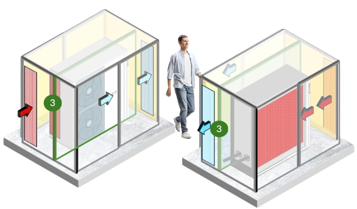
Standard air ductingOur most frequently installed version. The air inlet is at the rear side, right or left and at the front side offset to the right or left. The mirror-inverted design allows the side of the air inlet and air outlet to be selected flexibly during installation on site. Due to the laterally offset air inlet and air outlet, an air short circuit between the incoming warm air and the outgoing cold air is excluded, even in windy weather conditions.
3) Thermal and hermetic separation of the air chambers Disadvantage There must be no obstacles at the sides of the air inlet and outlet at a distance of around 50 cm. |
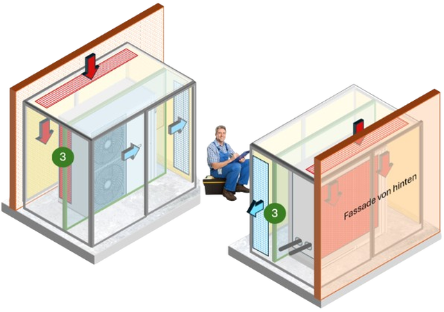
Air intake through the roofThe air inlet through the roof is suitable for direct installation of the acoustic bonnet parallel to the house façade and in the case of existing lateral obstacles at the air inlet. With this variant, the bonnet can be installed at a distance of 1 cm from the house façade.
The acoustic bonnet can thus be installed on one side and the rear directly in front of an obstacle. Disadvantages Reduced weather protection due to the air inlet openings in the roof. The service doors at the rear can no longer be removed. This means that service access is from the front and both sides |
Air intake from the rear
|
Enables installation in front of a lateral obstacle, such as a garden wall or a wall. The air flows directly to the evaporator without deflection. The air outlet is deflected to the front at a 90° angle and the air outlet sound is therefore broken up.
The weather protection is significantly improved compared to an air inlet via the wall. Disadvantages The service doors on one side can no longer be opened. Sound reduction is reduced towards the rear, and the sound can be reflected by nearby obstacles behind the rear of the acoustic bonnet. |
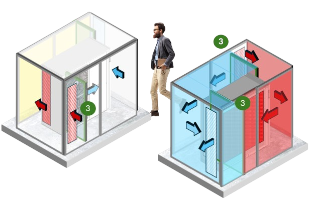
Labyrinth systemThe air routing principle is based on deflecting the exhaust air twice, each time at a 90° angle. This enables us to achieve maximum noise reduction. However, this comes at the cost of a higher pressure loss in systems with fans with low static pressure.
The air inlet is at the front or at the side of the front. The incoming air is channelled directly to the evaporator. The outgoing air is channelled to the side at a 90° angle at the front and then diverted back to the rear at a 90° angle. Disadvantages Pressure loss > than 20 Pascal For systems with an additional side evaporator, the air inlet duct must be positioned very precisely to prevent the side evaporator from being covered. Installation is more complex than with the aforementioned air routing methods. |
Sound enclosures Basic properties |
|
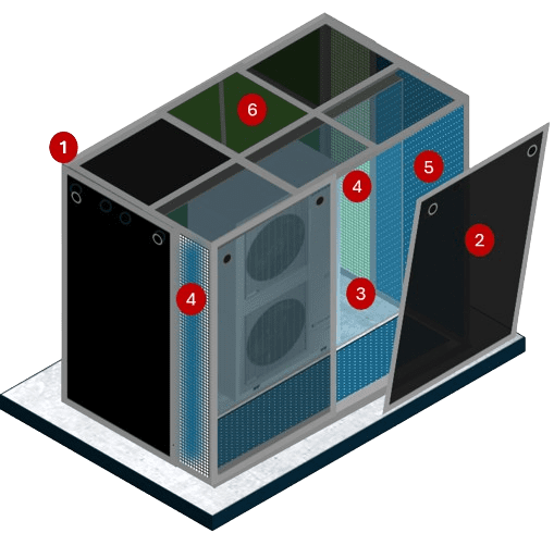
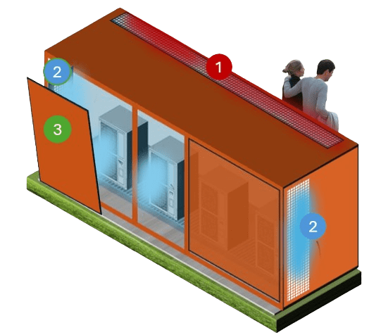
1 ) Sound enclosure base frame made of aluminium plug-in profiles. 2 ) Service doors around the system with internal 40 mm insulation. 3 ) Hermetic separation of the air inlet from the air outlet by using a plate for separation. 4 ) Freely selectable air routing thanks to the mirror-inverted design of the ventilation elements. 5 ) Sound insulation insensitive to water, does not build up mould and is flame-retardant. 6 ) Sound enclosure roof with a load capacity of 160 kg/m2 |
The base frame of our acoustic enclosures is based on aluminium plug-in profile frames with a thickness of 55 mm. Service doors are installed in these frames around the systems to ensure unhindered access for service and maintenance work at all times.
The service doors are based on aluminium panels with a thickness of 1.5 mm with 40 mm thick Stratocell® Whisper insulation on the inside, the material has some of the best sound-absorbing properties available on the market. As the laminated polyethylene foam absorbs sound and does not reflect it, it is an excellent alternative to many of the sound insulation materials used today. The insulation is also moisture-resistant, does not build up mould, can be rinsed with a high-pressure cleaner and complies with fire protection class: B-S2-d0 (flame-retardant).
The acoustic bonnets are designed for the required air volume of the systems so that they can be operated without loss of performance despite the sound insulation. It should be noted that the dimensions of the acoustic enclosures can vary considerably for devices with the same dimensions due to the required air volumes. A simple modification of the fan blades and/or an increased fan speed can result in systems with very different air volumes despite the same dimensions.
The free air inlet and outlet openings are always designed slightly above the maximum required air volume of the system. The air routing (air inlet / air outlet)
is offset to the side so that no air short circuit can occur between the exhaust air and supply air, which would massively reduce the system performance.
Sound enclosures for systems with single and double fans |
|
When dimensioning the size of the acoustic enclosure, it is not the physical dimensions of the system that are decisive, but the required air volume of the heat pump or air conditioning system in order to be able to operate it without power and pressure losses.
As most systems are equipped with axial fans with a low static pressure of max. 20 Pa, the free air inlet and air outlet surfaces are designed for an air velocity of 3 to 4 metres/sec. This value applies to both air conditioning systems and air source heat pumps. Conclusion It is not possible to standardise the dimensions of acoustic enclosures; the design is always based on the required air volume under full load of the system. |
Sound enclosures for heat pump cascades |
|
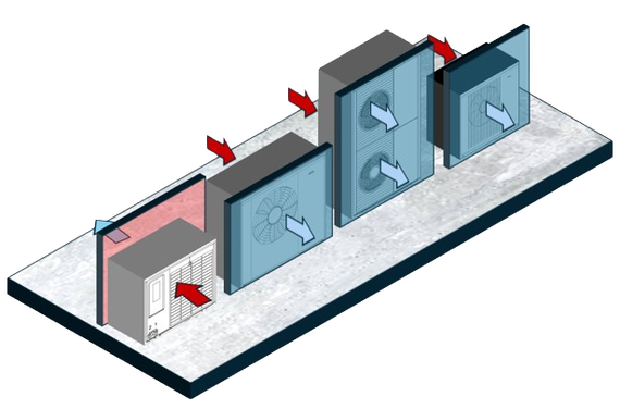
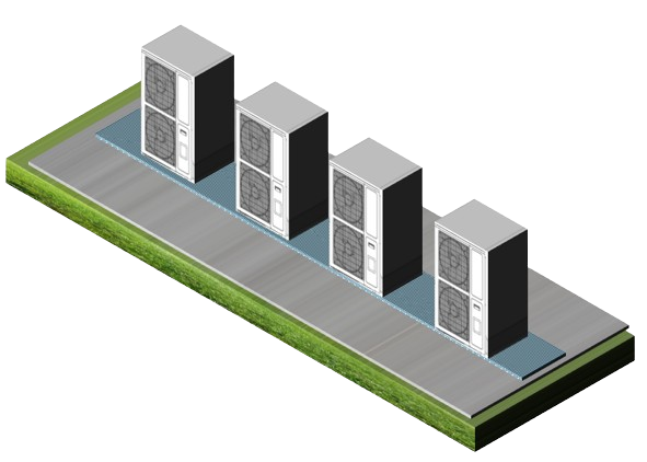
In a cascade of air/water heat pumps, the systems are interconnected in such a way that the heating output can be flexibly adapted to the respective heat demand and a certain degree of redundancy is also created in the event of a system failure. The cascading of heat pumps is often realised today where a greater heat requirement exceeds the heating output of a single system during peak cooling periods.
Cascade circuits can be realised with both on/off heat pumps and heat pumps with inverter technology. It should be noted that cascading changes the assessment of the noise emissions of the heat pumps. It is important that the calculation does not simply add the decibel levels of the individual systems, which are not a physical quantity. For the calculation, the sound levels must first be converted back into sound pressures, the sum of which is then used to form a sound level. This means that a heat pump cascade also has a clear advantage over distributed individual systems when assessing sound values, as the total sound pressure level of two equally loud heat pumps, for example, is only 3 dB(A) higher than that of a single system, even though the sound power has doubled with the installation of two identical systems. |
Increase in sound power according to the number of systems in series connection*
1 system = sound power increase = 0 dB(A) 2 systems = increase in sound power = 3 dB(A) 4 systems = increase in sound power = 6 dB(A) *This calculation is based on the assumption that all systems always run in the same operating mode. As a consequence, this is a purely theoretical consideration which is also used for the sound calculation of several sound sources for the assessment by authorities. As the systems are often located a short distance from each other, it should be noted that wind at the front of the system also causes the cold air to be recirculated to the condensers, which can lead to a reduction in system output. This is where our acoustic bonnets can help, allowing the cold air to be discharged in a targeted manner without causing an air short circuit, even if the units are installed close together. 1) Air In 2) Air Out 3) Removable service doors around the systems |
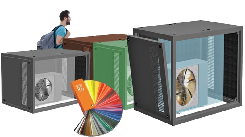
Free choice of RAL exterior colour for your acoustic enclosure |
|
I would like to find out what colour a physical object is (example facade) How do I do this?
We recommend comparing the colour of the object with the colour samples in a physical colour fan. Please note that it may also be a RAL colour or a colour from another colour system used by a specific paint manufacturer, for example. You should also bear in mind that the colour on the object may have faded over time. RAL offers an electronic device that determines a RAL colour by "scanning" the object. Caution: From an energy point of view, we recommend light colours for air conditioning systems and dark colours for heat pumps, which heat up more in the sun. |

