|
Why green roofs? |
|
Green buildings retain rainwater, humidify the air, cool, reduce noise and filter dust and pollutants. Carefully designed roof gardens not only provide a habitat for animals and plants, but also serve as a recreational area.
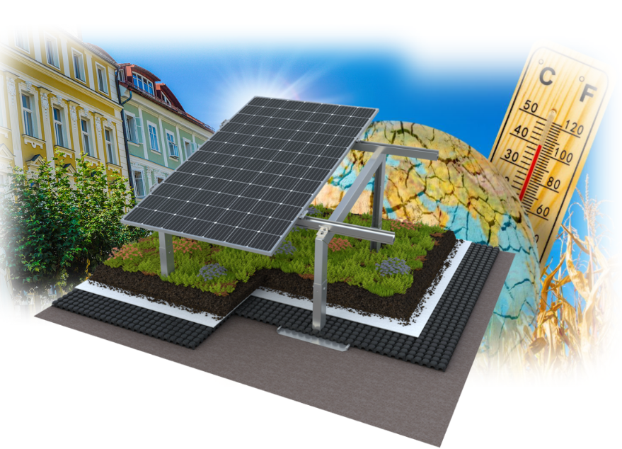
Such green roof areas provide a visual enhancement of urban areas and thus improve the cityscape. From an economic point of view, green roofs can reduce operating costs and energy consumption. Due to their cooling effect, green roofs increase the yield of solar systems. As green roofs equalise the temperature and protect against UV rays, the service life of the roofs can almost double. This also makes the operation of the building more favourable. With our green roofs, green areas of a few square metres up to > 50m2 can be created for sound enclosures for large heat pumps or cooling systems. |
Green roofs and surface temperature
Green roofs have significantly lower surface temperatures and temperature fluctuations than conventional roofs, which leads to a considerable reduction in warming.
Temperature differences
Conventional bitumen roofs can reach temperatures of up to 80-90°C in summer, gravel roofs can heat up to 50°C. Green roofs, on the other hand, reach a maximum of 20-35°C.
Concrete examples
In Chicago, summer temperatures on a green roof fluctuated between 33°C and 48°C, while a conventional roof reached temperatures of up to 76°C.
Singapore even showed a temperature decrease of up to 18°C after the installation of a green roof.
Impact on the building
The lower heating of green roofs leads to a reduction of heat gain by 92-97% compared to conventional roof systems during the warm season. This helps to improve the energy balance of buildings and reduces energy consumption, especially in the attic.
Impact on the urban climate
Green roofs can reduce the ambient temperature in cities by 0.3 to 3°C, thus significantly reducing the urban heat island effect. In a study in Germany, the average reduction in air temperature due to green roofs was 1.34°C.
Green roofs around heat pumps and air conditioners |
|
The high-density construction method means that there is a lack of green spaces in cities. In addition, heat pumps and air conditioning units are often located in courtyards and often do not meet the aesthetic requirements of local residents.
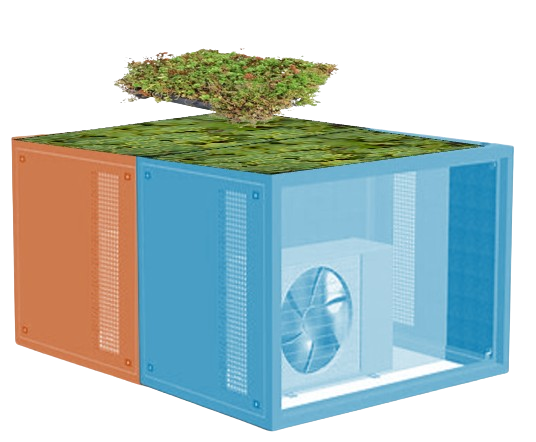
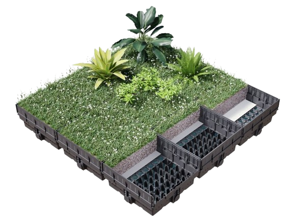
Our green noise protection hoods are visually appealing thanks to the free choice of RAL colour in combination with the plants. They also make an important contribution to the fight against climate change. Green sedum plants, which require little water and sunlight, are particularly suitable for planting on noise abatement hoods and in the area of refrigeration systems. The roof, designed as a planting tray, offers the plants a depth of 20 cm. A filter fleece is integrated into the tray. A mixture of perlite and potting soil is suitable as a substrate. This combination allows the planting tub to be filled without a lot of weight and provides the plants with an ideal structure for root formation. This advantage naturally also applies to the planting of cooling and photovoltaic systems. |
Green roofs increase energy and acoustic comfort |
|
The layering on the acoustic bonnet roof also increases acoustic comfort and further increases sound insulation from above.
Energy benefits Air conditioning systems The use of acoustic enclosures for air conditioning systems also reduces the heating of the acoustic enclosure in direct sunlight and thus reduces the delta T between the outside air and the required cooling capacity. Heat pumps When used with heat pumps, the layering in the plant tray serves as a kind of external insulation and creates a slightly warmer environment, which in turn can lead to a reduction in the energy-intensive de-icing cycles for heat pumps. Solar Inverters Inverters should always be installed in a cool place. The losses that inevitably occur during the transformation from DC to AC voltage are dissipated into the ambient air in the form of heat. The cooler the environment, the better the heat can be dissipated. Cooling takes place either via cooling fins or via fans integrated in the inverter. |
Sedum Plants |
|
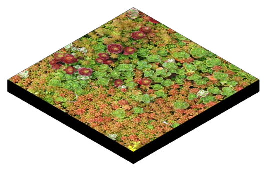
Sedum belongs to the stonecrop family (Crassulaceae) and is a fairly undemanding groundcover. Also known as stonecrop or fat hen, Sedum is particularly diverse, with around 420 different species.
Sedum plants are not only ideal perennials for rock gardens, but are also preferred for green roofs. These sedum ground covers not only provide excellent insulation, they also look wonderful. In the garden, on the other hand, sedum is mostly used to beautify rock gardens and is also very suitable for planting on graves. Due to its properties, it can be said that sedum is by far the most popular plant for rock and roof greening and front gardens. |
Ready-made-Sedum Boxes |

